Agostino G. Bruzzone, Roberto Mosca, Roberto Revetria
DIP – Dipartimento di Ingegneria della Produzione
Via Opera Pia, 15 - 16145 Genova GE, Italy
URL: http://st.itim.unige.it
Email: {agostino, roberto, revetria}@itim.unige.it
ABSTRACT
One of the major issues in Supply Chain Management and
in Distributed Production Management is related to the various interactions
between the various partners. Such subject was, traditionally, addressed
to the Game Theory in order to be solved. By this approach some interesting
result have been obtained in the past, therefore the principal limitation
of such approach is the a priori static framework in which the problem
is formulated, while the reality correspond to a dynamic environment. The
proposed paper focuses its attention to the integration of modelling techniques
and High Level Architecture (HLA) with Nash Equilibrium Theory. This is
devoted to study dynamically the complex interaction phenomena of the various
Supply Chain actors; particularly the Authors present and discuss the integration
of a Logistic Vector in a Distributed HLA Simulation as well as the implementation
of a complete set of negotiation rules between the actors (HLA federates).
The modelling and Simulation issues as well as learned lessons are presented
and summarised.
INTRODUCTION
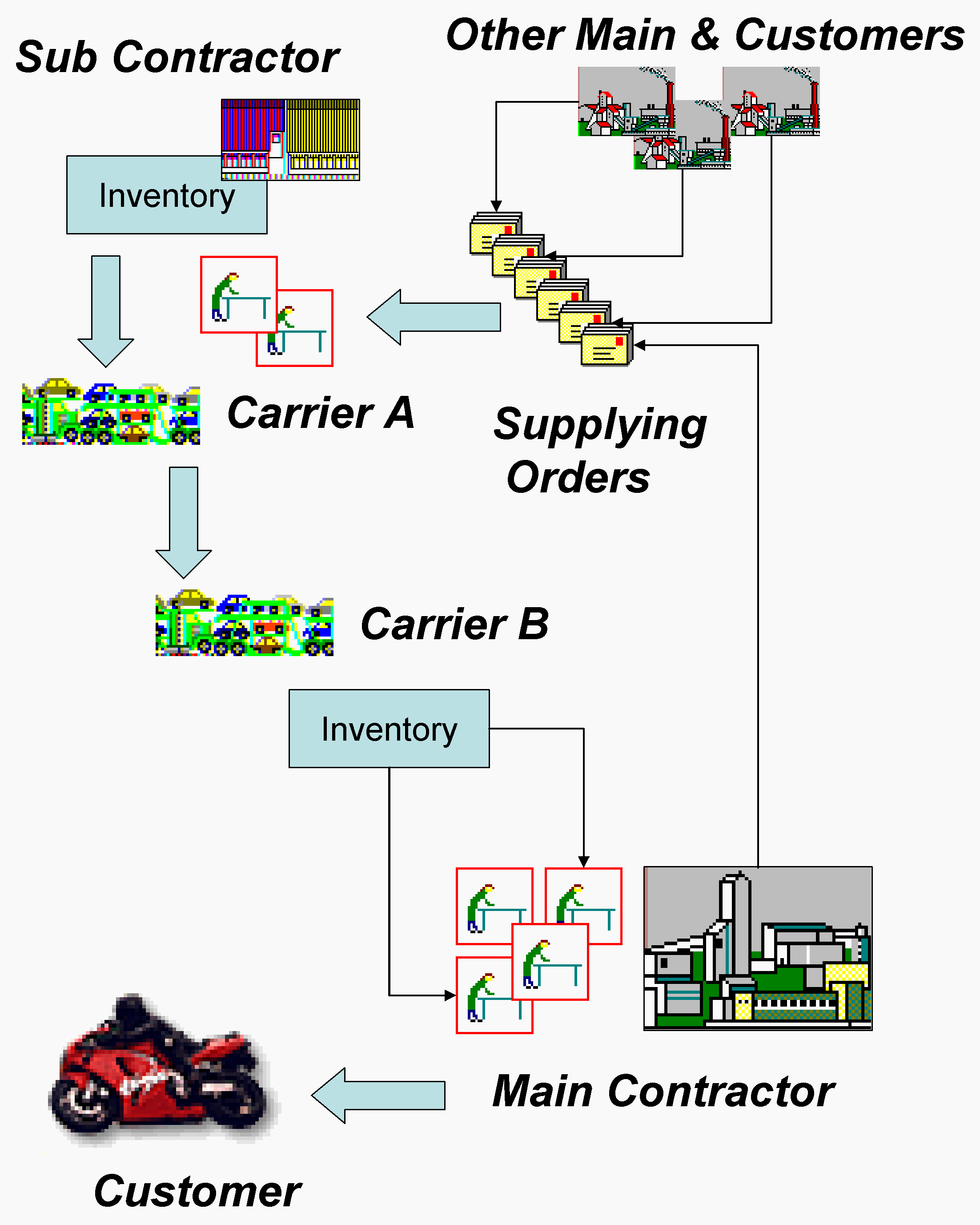
Due to the rapid transformation of the production process
into a distributed based structure the needs of new approach for the improvement
of performances have raised to a critical point.
 |
| Figure 1: The Supply Chain Model |
The optimisation of a production line is now not only
a matter of a single production site but is becoming a shared goal of the
entire Supply Chain. Since in centralised production organisation each
actor of the system has the same objective function (i.e. reducing costs,
increasing production rate, etc.) in a distributed environment each subject
has its own target to achieve. As simple example we can consider the Main
Contractor (M): an assembly line that produces parts by integrating several
components coming from various Sub Contractors. For the simplest case we
consider only a spare part produced by a single Sub Contractor (S). While
M is doing its best in order to guarantee the respect of the due date pushing
the assembly process, S is working in order to assure the optimal saturation
of its production resources (i.e. Working Centres, Workers, Milling Machines,
etc.). In the case in which S will be not able to satisfy the supplying
due date also M will suffer such delay introducing eventually a delay in
the final assembly due date and consequent problems (i.e. bad quality image,
penalties etc.). The common practice to avoid such risk is to put penalties
in the outsourcing contracts and to increase the Safety Stocks of the various
spare parts. Such practice has demonstrate to be inefficient since doesn’t
guarantee M from the risk of shortage or stock-out in case of S fails to
meet its requirements and the applied penalties are not able to compensate
the M costs suffered for a Final Due Date Delay. The implemented approach
is able, by converse, to help managers to improve the production Program
& Schedule in order to reduce the risk of a Stock-out due to S.
SIMPLE NEGOTIATION PROTOCOL
The test case we have outlined in the previous paragraph
can be extended by considering the integration of a SME (Small & Medium
Enterprise) in the supply chain.Due to the specialization of the various
subject in the supply chain is even more frequent that SME take care about
specialized operation (i.e. Thermal Treatment, Recoating, Special Parts
Production, etc.) that are usually critical, but not very expensive if
compared to others in the production budget. In this case the penalties
usually applicable for each day of delay cannot exceed a fixed fraction
of the value of the supplying. In the awful case of delay S will pay a
strong, for its point of view, penalty and M will suffer the same delay
by paying a much higher penalty to its customer.
 |
| Figure 2: Simple Negotiation Process |
In formula we can express as follow:
![]() (1)
(1)
| The Total Balance Due by M | €/unit | |
| % Penalty Paid by M for Delay | -/day | |
| % Penalty Paid by S for Delay | -/day | |
| Value of M’s Finished Product | €/unit | |
| Values of S’s Part | €/unit | |
| Due Date Delay | days |
In this way is possible to note that the "penalty practice" in the outsourcing contract will have as only effect a slight reduction in the Balance to pay not considering the cost coming from the image loss.
The only way to reduce the costs coming from unexpected delay in distributed production process are related to the possibility of reduce the effect of a delay to the final assembly process.
Based of this approach the key aspect of the methodology is the value of an early information of a possible delay coming from the Sub Contractor to the main.
In real life application, in fact, the main contractor has several production processes running at the same time with different advancing.
If a parts that is waited by an assembly line expected to be in delay, the production manager can change the work schedule by changing the priority of the job and use the idle resource in order to increase other products advancing.
In this way the final cost of the delay will be compensated by the increase of the resources utilisation if properly addressed.
The feasibility of production schedule rearrangements is strictly related to the possibility of evaluate the impact of the Sub Contractor delays in the Main Contractor production processes.
Such evaluation is possible by using both simulation and meta-models; in the first case the computational effort could be too high for on-line real-time applications, while second approach need to be re-tuned and validated for each new space analysis area.
Due to these considerations in our application meta-modeling has to be used.
The proposed methodology is, therefore, outlined in the following example.
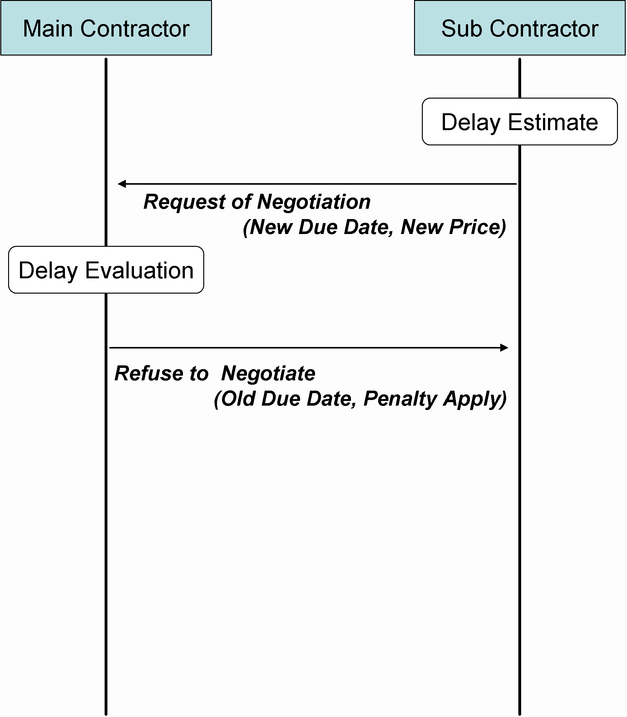
The Sub Contractor is evaluating a situation in which it will be not able to meet its due dates and so he decides to inform the Main Contractor by proposing a new Due Date and a discounted price. Main Contractor will evaluate the proposal and decide to accept or to refuse the proposal.
In the figure 2 such simple negotiation process is shown
and it identifies two critical issues: the Sub Contractor Delay Estimate
and the Main Contractor Delay Evaluation. The output of the first process
is an delay estimation for supplying parts from the Sub Contractor, so
is measured in terms of days or Unit of Time (UT). While the output of
the second issue is the cost estimation corresponding to the event "Sub
Contractor failing to meet the due date". It is possible to identify several
conditions in which such process will take place, particularly (Bruzzone
2002) we identified a static-deterministic scenario and a dynamic-stochastic
one.
 |
| Figure 3: Critical Path Identification in Step 2 |
Static – Deterministic Case
In the first case we consider an assembly process described by a PERT graph where the various parts are required along the activities [13]. The simplest Delay Estimation Process can be summarize as follow:
Delay Estimate
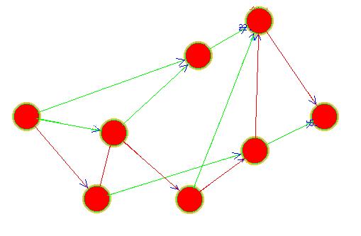
Step 1: The dj –duration of j-th activity are used to estimate the Early Start and Finish Dates as well as the Late Start and Finish Date.
Step 2: Using the Forward and Backward Rules if possible to identify the Critical Path
Step 3: If the Sub Contractor has an Expected Delay of h days in the k-th activity with kÎCritical Path, the Sub Contractor will suffer a Delay in Supplying of h days.
Delay Evaluation
Step1: The same process could be used also to Evaluate the Delay by the Main Contractor by applying the first part of the (1) formula to the estimate delay of h days:
![]() (2)
(2)
In this case the Main Contractor will estimate the delay simply by calculating the difference between the New Due Date (Dnew) and the Old Due Date (Dold).
![]() (3)
(3)
Step 2: The Cost identified at Step 1 has to be corrected by subtracting the difference between the original price (Pold) and the new discounted price (Pnew).
![]() (4)
(4)
The final difference between the Cost of the Delay (2) and the Gain of the delay (4)will identify the Cost of the Opportunity to Accept the Negotiation.
Step 3:
The cost for the opportunity to refuse the negotiation could be calculated simply by apply the entire (1) formula to the estimated delay of h days.
![]() (5)
(5)
Step 4: Choose the negotiation opportunity with a lower cost, so:
![]() (6)
(6)
The Main Contractor in the outlined example has also the opportunity
to systematically refuse each negotiation by applying each time the penalty,
in this case the Evaluation of the Delay is done in one step only.
 |
| Figure 4: Delay Estimation in Static-Stochastic Case |
ADVANCED NEGOTIATION PROCESS
In real life the Negotiation process is much more complicated than presented, so Delay Estimation and Evaluation need to investigate also the impact of the stochastic components as well as to evaluate correctly Delays and Costs.
The simple example shown in the previous paragraph can be generalised by introducing a technique able to make an a priori estimation of the Probability to Meet the Due Date.
Static-Stochastic Case
In this case the estimation of the Delay can be extended by introducing the concept of expected duration of the elementary j-th activity.
Each dj it has, now, to be calculate
by evaluating 3 different duration estmate:
| a | Optimistic Duration Estimate |
| b | Pessimistic Duration Estimate |
| M0 | Modal Duration Estimate |
By using the Beta distribution is possible to calculate
the following parameter
|
|
Average duration for Activity j-th |
|
|
Variance Estimation of Duration of Activity j-th |
In this way is possible to define the following summary (7) as Probability Factor to have activity j-th in delay:
 (7)
(7)
where:
| Distributed as NID(0,s ) | |
| Late Finish Date for j-th Activity | |
| Early Finish Date for j-th Activity | |
| Variance of Late Finish Date for j-th Activity (Sum of s on Backward Rule) | |
| Variance of Early Finish Date for j-th Activity (Sum of s on Forward Rule) |
and by using the Standard Nornal Distribution table is possible to estimate the probability of a delay for activity j-th.
Such procedure could be summarized in the following step.
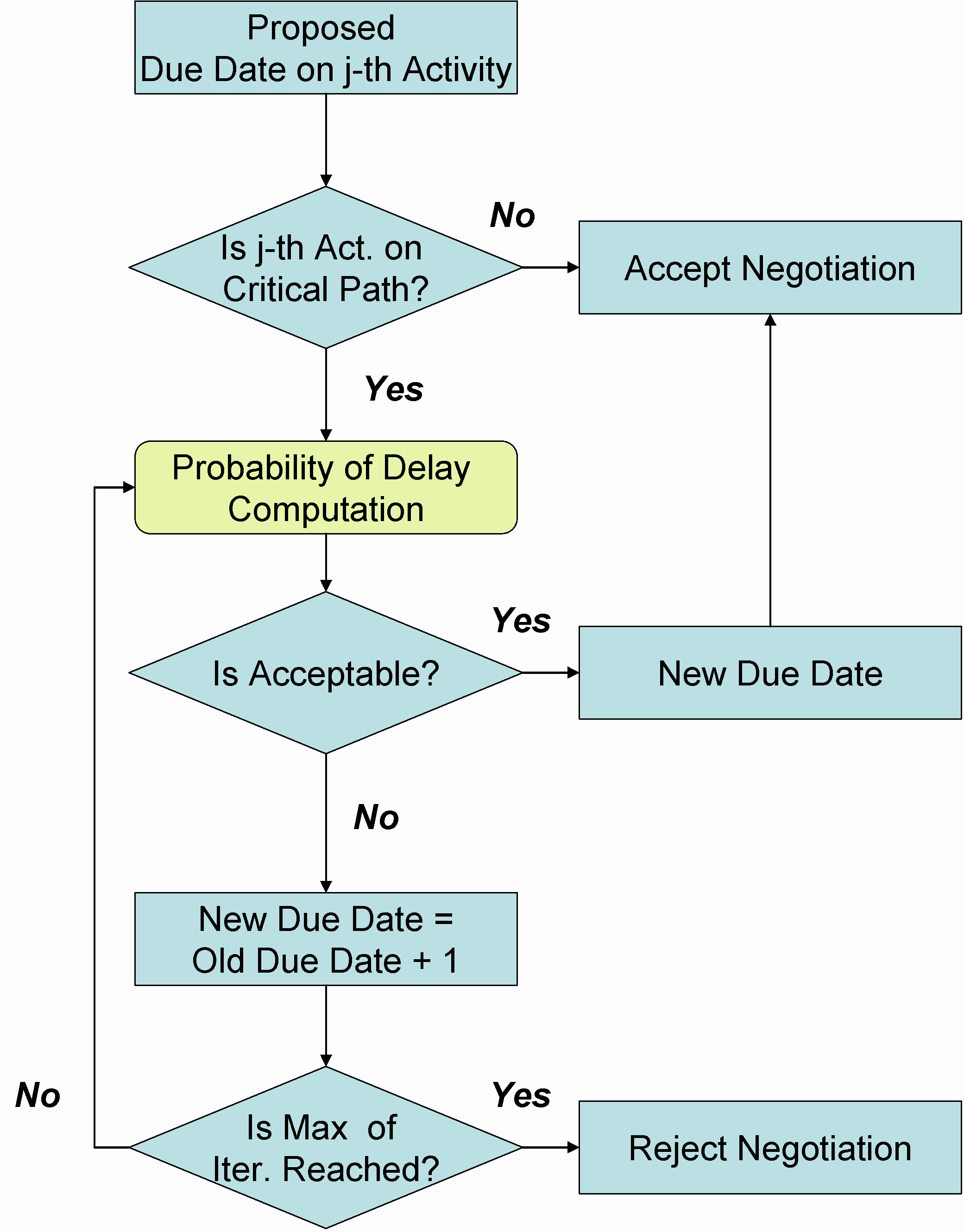
Probability of Delay and Delay Estimation
Step1: The Sub Contractor calculate the critical path of the its production process and evaluate the average durations as well as their variances.
Step 2: For the desired activity the Probability
Factor is calculated and the subsequent probability is calculated.
 |
| Figure 5 – Delay Evaluation in Static-Stochastic Case |
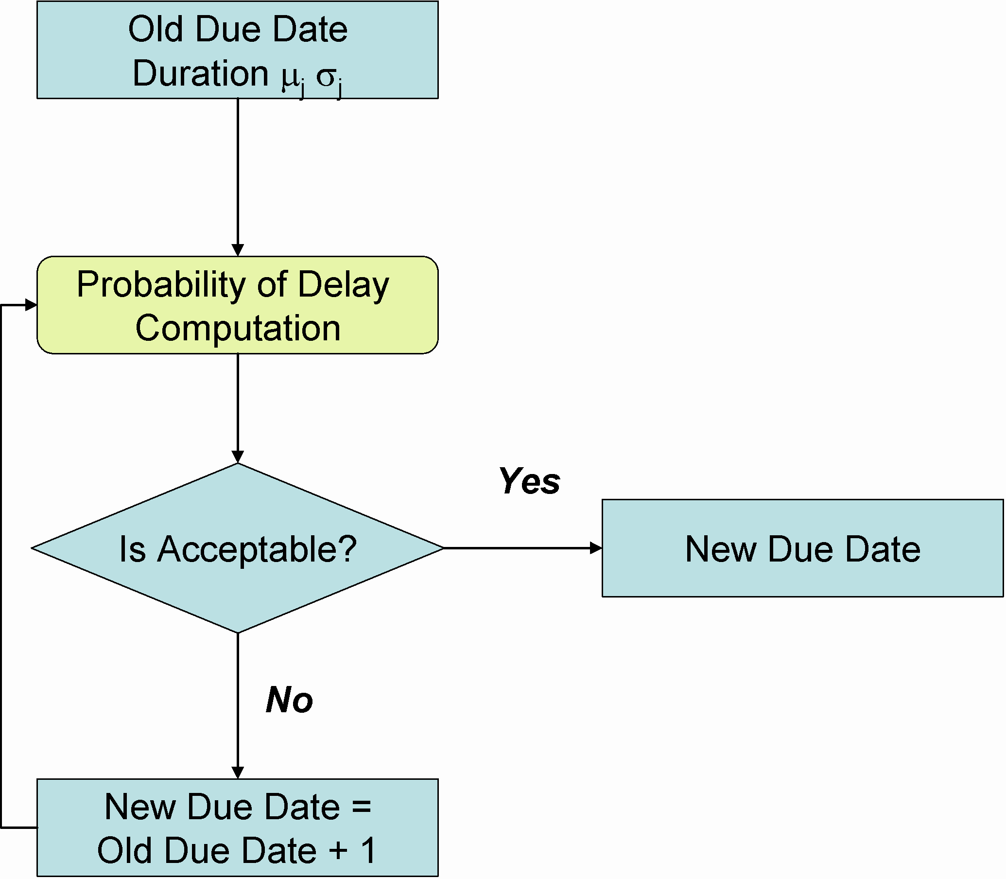
Step 3: Iteratively a new due date is proposed and the probability of delay is again calculated, if this value is lower than a predefine value (i.e. 2%) the new due date is fixed for the request for negotiation with the Main Contractor.
Main Contractor can use the same approach in order to evaluate the cost of the delay simply by calculating the expected delay on its completion date. The procedure for such evaluation is shown in figure 5 and summarized in the following step.
Delay Evaluation in a Static-Stochastic Case
Step 1: Recalculate the PERT of the final assembly process using the proposal due date, if the parts or the service is due out of an activity on the critical path it will not affect the final due date so accept the proposal from the Sub Contractor
Step 2: If the activity is on the critical path, use the (7) formula to calculate the risk to fail the final due date. If the probability is too high iterate the process till the new due date is determined.
Step 3: If the new due date still meet the customer needs accept the negotiation ore, in the opposite case refuse it .
In case of dynamic scenario the methodology needs to be extended in
order to proper evaluate the economic impact of the expected delay according
to the other entities in the Supply Chain. The resulting problem can be
successfully addressed by using the Nested Simulation Paradigm (Kindler
2000), but the computational effort will result in several cases too much
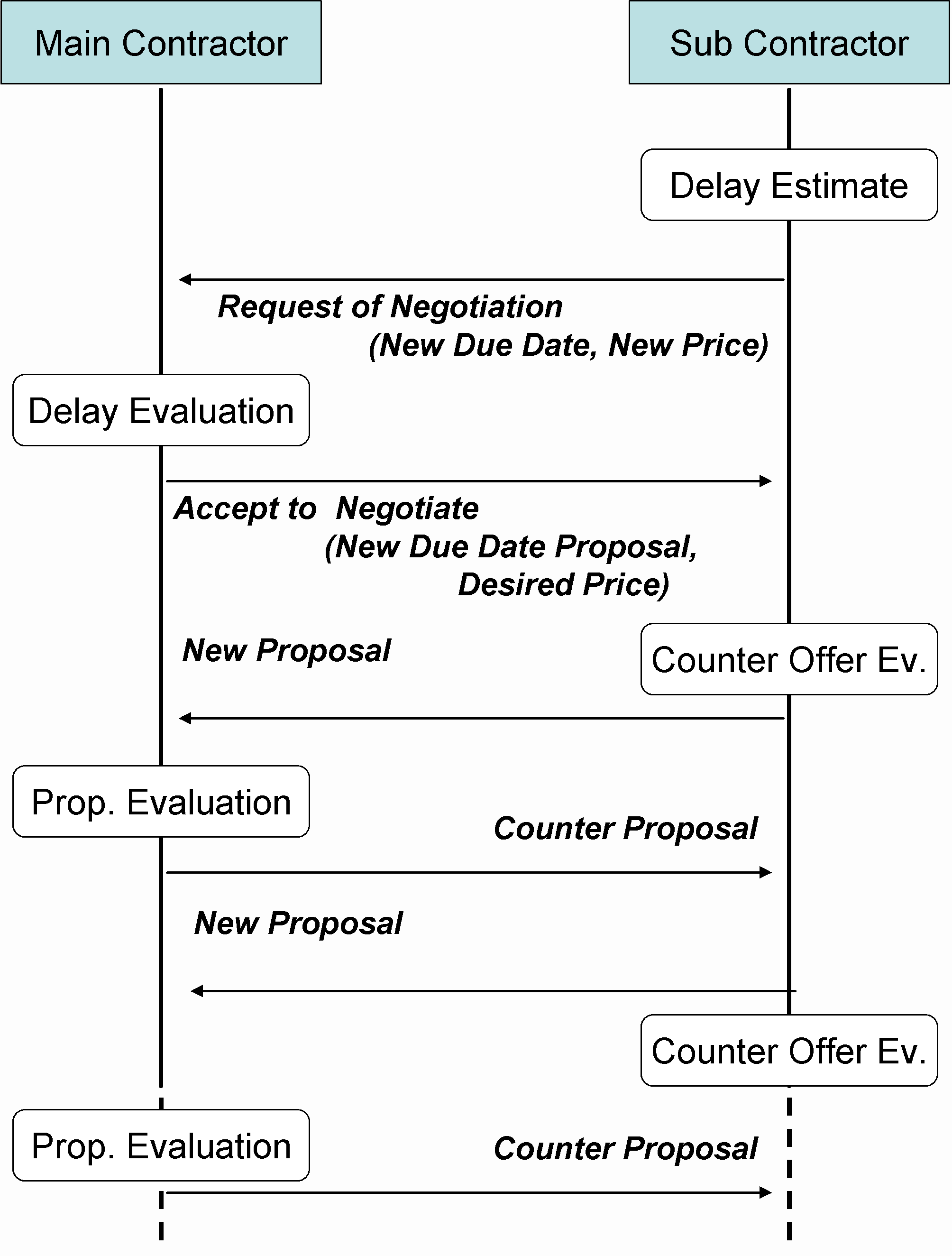
high to be used. In the dynamic scenario, in fact, the negotiation process
is done iteratively, until an agreement is reached or the negotiation is
broken, for each simulation event in which the Sub Contractor is asking
for a new Due Date specification.
 |
| Figure 6: Negotiation in Dynamic-Stochastic Scenario |
In several cases also the Main Contractor could ask for a negotiation, this is the case in which the final assembly is in late and the Main Contractor Project Manager asks for a delay in supply in order to reduce the inventory costs. The above conditions are met especially when Sub Contractors have different relationship also with other customers to whom they guarantee a higher priority. The SM&E Main Contractor, in fact has no enough power to compete with a large Outsourcer and so, sometimes, it is forced to accept unexpected delay on its supplying. The general approach is proposed than in figure 6 where is possible to note that inside the Delay Evaluation the Main Contractor has to use Nested Simulation.
In order to take advantage of the practical use of the methodology without the needs for a nested simulation a meta-modelling approach is then presented. The basic concept is related to the opportunity to substitute the nested simulator with a numerical model able to calculate the expected cost for a predefined delay. In this way is possible to identify the cost level of each offer presented by the actors in the Supply Chain and make the correct trade-off.
The cost resulting from a reschedule of an activity in the final assembly can be calculated in term of:
![]() (8)
(8)
where:
| Coefficient of Perceived Value | |
| Market Value of the Product | |
| Number of Unit of Time of Delay | |
| Maximum Delay Acceptable by Customer |
The Coefficient of Perceived Value is a subjective evaluation of the customer expectation from the product, can vary from a number less than one (no expectation) to some units (great expectation).
The Costs for Inventory and the WIP Costs are obtained by notice that a delay in an assembly phase can postpone the utilization of the parts used in the next steps and decrease the inventory turnover ratio as well as "anticipate" some machining on other parts. As meta-model the such costs are then proportional both to the Assembly Logic Inventory level and to the amplitude of the delay. The Assembly Logic Inventory parameter can be calculated as difference between the Budget Cost of the Work Performed (BCWP) and the Budget Cost of the Work Scheduled (BCWS).
As known from literature the difference between BCWP and BCWS in a measure of the advancing in the material acquisition and work performed.
![]() (9)
(9)
| Inventory and WIP Costs for a Delay of h Unit of Time | |
| Coefficient of Inv. and WIP Costs [0.2 – 0.8] | |
| Expected Delay |
The costs from Unefficiency are obtained by notice that the working force was designed for a pre-defined Work Schedule and now, due to the delay in supplying, some working activities cannot take place and while the resource are already hired or acquired. Such cost is simply proportional to the net number of resource multiply by their current retribution and the amplitude of the delay.
![]() (10)
(10)
| Cost for Unefficiency | |
| Numbero of Workers | |
| Retribution per Worker per Unit of Time | |
| Number of Machines | |
| Cost for Each Machine per Unit of Time |
By using the formula (5) (9) (8) and (10) is possible to write the following expression that identify the Trade-off between the cost and benefits of the Negotiation

MODELLING A LOGISTIC PLATFORM
The proposed example is related to the modelling of a complete supply chain that produces business planes: the main assembly line is located in Genoa, Italy while the major supplier and outsourcer are spread all around the Italian peninsula. The name for the project was fixed in WILD – Web Integrated Logistic Designer and was a research project sponsored by the Italian Ministry of Research (MIUR), and the aim was to demonstrate the practical use of the proposed methodology in support the management of a complex Supply Chain.
Since the WILD project was designed based on a two step approach, the first phase has regarded the demonstration of a High Level Architecture Federation able to simulate the various actors in a Supply Chain. On such part, the real life example was developed by 7 Universities (DIP University of Genoa, DE Universita` dell'Aquila, DIG Politecnico Milano, DIMEC University of Salerno, DIMEG Politecnico di Bari, DPGI University of Naples, SITI University of Florence) co-ordinated by the Authors. Each of the partners was involved in modelling and integrating a supplier into the federation. As second step, WILD Federation was extended in order to include the Transportation Federate, the Logistic Federate and the Negotiation Process. Particularly this last topic was introduced in order to support the development of the new Supply Chain Managing approach presented in the previous paragraph. The initial OMT (Object Model Template) was extended in order to provide a model for the integration of the Logistic Federate (Carrier and Terminal), and its general architecture is presented in table 1.
The various federates/simulators were build by using several different Simulation Tools (i.e. Arena™, Simple++™) as well as General Purpose Language (i.e. Java™, C/C++) in order to demonstrate the practical interoperability of the proposed HLA framework. The integration of the COTS Simulator into HLA federation was obtained by implementing HORUS (HLA Operative Relay Using Sockets) a middleware developed by the authors that relies all the events from the simulation and from the federation to the COTS simulator by using TCP/IP Sockets.
Such approach has demonstrate to be very effective in
reduce the implementation efforts since it separate all the HLA programming,
usually done in C/C++ or in Java from the modelling phase. In this way
people concentrate their activity only in defining the simulation logic
rather than hardcoding the HLA software. The implementation of the outlined
federation using HORUS and HORUS-Based approach has required also the integration
of the COTS package with a customized interface for the HORUS-COTS information
exchange, this last part was implemented in MS-Visual Basic for Application™
(VBA).
| Table 1: WILD II – Object Model Template | ||
| Objects
Attribute Supplier Customer Logistic HLA Order Name Publish Subscribe -
ID Publish Subscribe -
Quantity Publish Subscribe -
Date Publish Subscribe -
From Publish Subscribe -
To Publish Subscribe - HLAPF Name Subscribe Publish - |
ID
Subscribe Publish -
Quantity Subscribe Publish - From Subscribe Publish -
To Subscribe Publish - Pick_Up_
Request_for_
Publish - Subscribe
Parking_Lot Publish
Publish
Last_Pick_
Publish - Subscribe |
Delivery_
Items_
- Subscribe Publish
Parking_lot Publish
Publish
Items_
- Publish Subscribe HLA Invoice Deliveries_to_
Subscribe - Publish
|
LOGISTIC VECTORS
The Logistic Federate implements all the aspect and the logic of two Logistic Object: the Terminal and the Carrier. The purpose of the Terminal was, in this exercise, to coordinate the shipping process among federates and two assure that the logistics procedures will affect the shipment procedures as it will happen in reality. The basic logic was designed as a set of module in which each component can be connected to the others without the needs of redesign the entire federation.
Federate Carrier
The federate carrier is a basic Logistic Module that is
modelling the process of transport products along a network between a source
and a destination. The network design was fixed using an oriented graph.
In such structure each node is a physical location while the arc that connect
the nodes are the feasible routes among the nodes.
| Table 2: The Attribute Codification | ||
|
#1 #2 #3 #4 #5 Request
FROM TO CARRIER KIND ITEMS
|
Up_List FROM TO CARRIER KIND ITEMS Park_Lot FROM TO CARRIER VEHICLE ID CAPACITY
|
Delivere FROM TO CARRIER KIND ITEMS Items_
FROM TO CARRIER KIND ITEMS
|
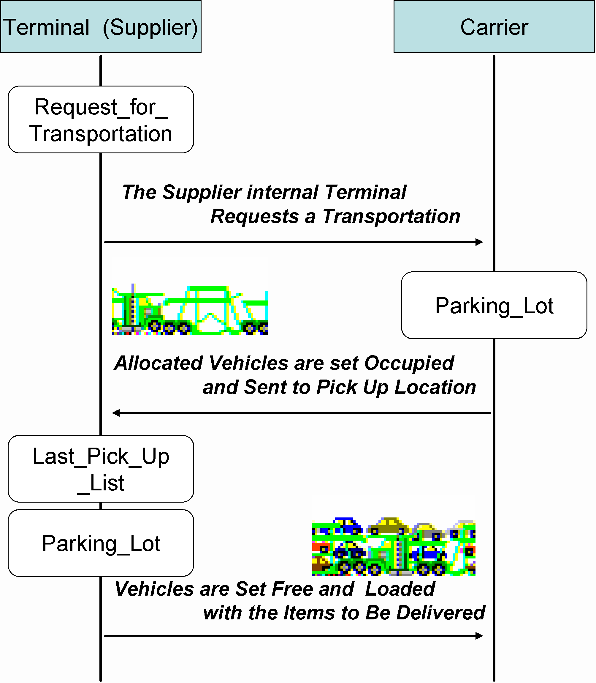
Each module can receive a list of items to be shipped and it decide the routing among the various possibilities in the graph according to its internal logic. The HLA object designed for its implementation is the Pick_Up_Location. Each federate that has to ship a parcel must publish the attribute Request_for_Transportation with a list of items to be shipped coded as follow.
As soon as the Federate Logistic will reflect the update it will start to process the request by sending to the location identified by element #1 in the attribute an update of the Attribute Park_Lot with a list of vehicle for the pick up procedure. As soon as the loading operation are finished the Supplier will update the attribute Last_Pick_Up_List with the list of items loaded on the vehicle. By using HLA the carrier will obtain a local copy of the items to be shipped and the routing procedure will identify the better route to get to destination. The routing is obtained by matching the elements #2 #4 #5 with the internal routing list and by process the shipping in the simulator itself. Each request for transportation is coded with the id of the carrier (see #3 element on the attribute) so each "listening" carrier federate can identify its own simply by filtering the reflect Request_for_Transportation attribute. The modularity of the approach can guarantee also multi-carrier based shipping; at the end of its transportation process each carrier simply update the #3 element in the attribute with the value of the #2 element if it has reach its final destination or the id of a new carrier for the next leg of its journey. In this way on the next simulated step the next carrier federate will take care of it.
On its final destination the federate carrier will update its attribute Items_Delivered and the Parking_Lot attribute with the list of the vehicles in delivering, as soon as the unloading operation will be over the Customer federate will update its attribute Items_Collected releasing at the same the delivering vehicles.
Federate Terminal
The concept of federate terminal is an extension of the
basic Module Logistic since the coordination of the loading/unloading operation
has to be proper evaluated.
 |
| Figure 7: The Terminal Federate |
Is a common practice, especially in the maritime sector, that when a vehicle is approaching the terminal the resource for the loading/unloading operation must be assigned in order to reduce the handling time at its minimum. Such event cannot be integrated in the simulator simply by mean of a stochastic delay. This because there is a kind of border event that depends from the availability of two classes of resources that belongs to different simulators: the handling resource in one hand (Terminal) and the vehicle approaching (Carrier). In order to reproduce such event the Terminal resource must reserve its resource by receiving the vehicle object in its internal event queue and process it according to its internal priority rules.
For this purpose the Carrier, in receiving the load for
example, will send its vehicle to the Supplier’s event queue until the
Supplier will send them back loaded. In this way if the loading resources
are occupied the carrier will have its vehicle idle on Supplier location
until the starting of the load event, by applying such procedure the real
life terminal logic will be respected. In the same way when the carrier
will notify the customer that the shipment is ready to be delivered, the
customer will receive on its internal event queue the list of the delivering
vehicle that will be used until the customer it will release it.
WILD HLA BASED IMPLEMENTATION
The implementation of the Negotiation Procedure is a key
aspect of the WILD II HLA Implementation since it will allow the entire
federation to work as Supply Chain DSS by applying the rules outlined in
the previous paragraphs. In such way managers will be able to improve the
performance of their production system by sharing common objectives and
take the proper decisions.
| Table 3: objectRoot.Negotiation Attributes |
| Attribute
Description UM ID_Order Is The ID of the Negotiating Order - ID_Facility Is The ID of the Facility that Requests Negotiation - New_Deadline N° Of Days of Delay Proposed by Initiator days PayOff Is the Penalty to be Applied €/day Date_Sub Is The Date Proposed by Sub-Contractor (Supplier) Date Date_Main Is the Date Proposed by Main Contractor (Customer) Date Agreement State of the Negotiation
- Counter Counter of Negotiation Attempt - ID_Turn Is the Next Federate that has to Reply to the Offer - |
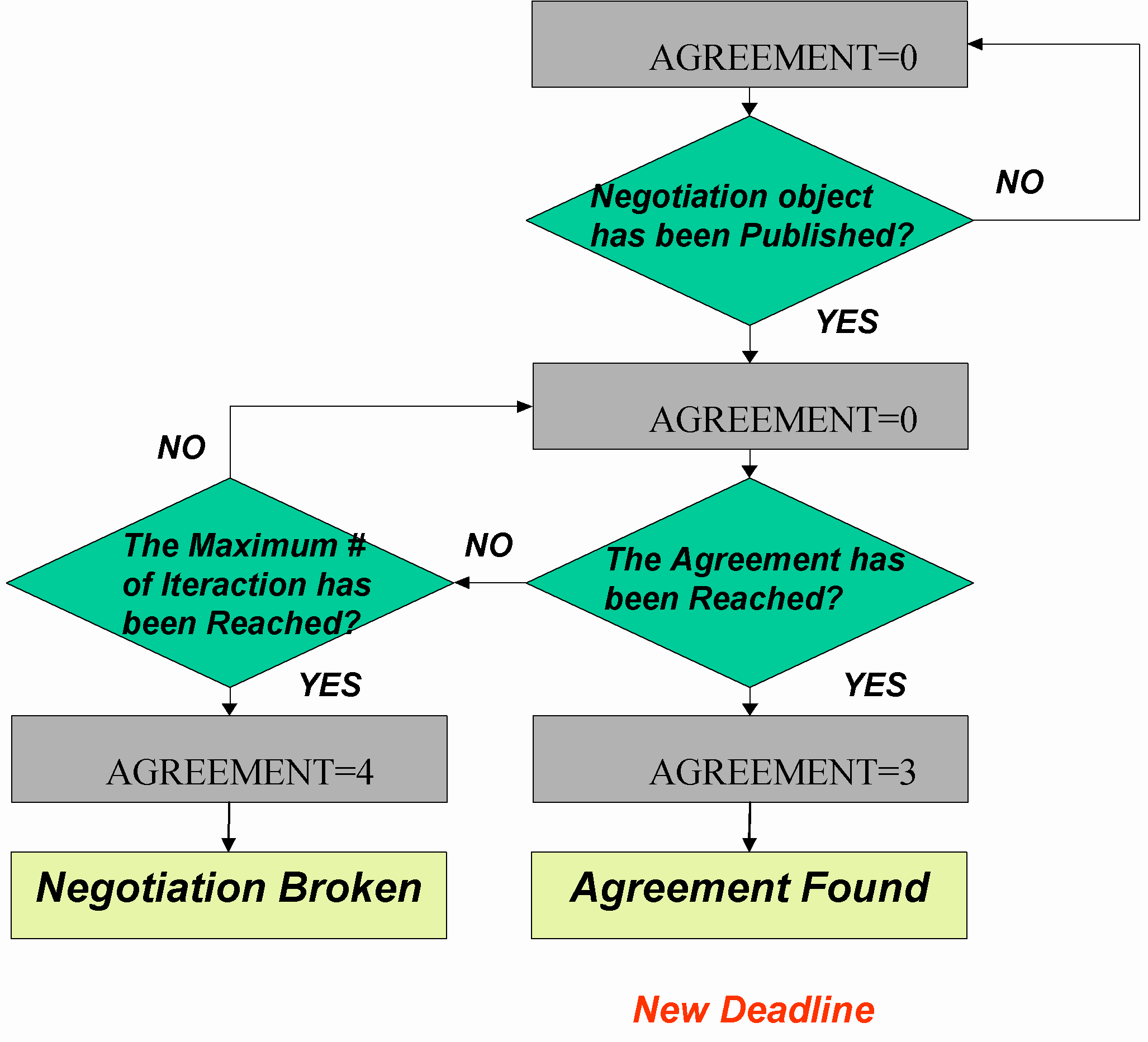
In order to integrate the negotiation procedures in the WILD federation the OMT has to be extended by introducing the object Negotiation with the following attributes.
Negotiation Process in WILD II Federation
Step 1
Each time a federate needs to redefine a due date it has to register a new instance of the object Negotiation and update the following attributes:
The responding federate (Id_Turn) will notify the initiating federate the penalty to be paid for the proposed delay by updating the following attributes:
At this point a new due date will be proposed and the negotiation will enter in the bidding phase. The originating federate (Main or Sub) will propose a new due date by updating the attributes:
The counterpart can have the opportunity to accept the proposal and stop the negotiation by updating the following attributes:
 |
| Figure 8: The WILD Negotiation Process |
CONCLUSIONS
The implemented methodology has proven to be very effective in building large and complex Supply Chain Simulation Federation. The use of such federation represents a new approach for the improvement of the various aspects in Network Based Production.
Particularly the presented issues have demonstrate the
practical application of the HLA framework to support distribute modelling
and simulation. The present real life example has demonstrated how COTS
software can be integrated into an HLA federation in order to model complex
logistic entities (i.e. Supplier, Carriers, Terminals, etc.). The major
advantages as well as the most important implementation issues have been
presented and discussed. As on-going research the authors introduced John
Nash’s Equilibrium Theory into the negotiation process in order to improve
the bidding performances of the algorithm.
 |
| Figure 9: John Nash’s Equilibrium Theory Module |
REFERENCES
BIBLIOGRAPHY
Agostino G. Bruzzone began his engineering studies at the Italian Naval Academy. He has been actively involved in the scientific community from several years as Director of the Genoa Center of MISS, Director of the SIMPLEST Technical Chapter of the SCS (Society for Computer Simulation international) and President of the Liophant Simulation Club. He has written more than 100 scientific papers in addition to technical and professional reports in partnerships with major companies (i.e. IBM, Fiat Group, Contship, Solvay) and agencies (i.e. Italian Navy, NASA, NCS, US Army).
Roberto Mosca is Full Professor of "Industrial Plants Management" and "Economy and Business Organization" at the Institute of Technology and Mechanical Plants, University of Genoa. He has worked in the simulation sector since 1969 using discrete and stochastic industrial simulators for off-line and on-line applications. His research work focuses on the evaluation of simulation languages and new modeling techniques and his research team is developing new AI applications for industrial plant management. Currently he is Director of DIP in Genoa University.
Roberto Revetria earned his degree in mechanical
engineering at the University of Genoa and he completed his master thesis
in Genoa Mass Transportation Company developing an automatic system integrating
ANN (Artificial Neural Networks) and simulation with the ERP (Enterprise
Resource Planning) for supporting purchasing activities. He had consulting
experience in modeling applied to environmental management for the new
Bosch plant facility TDI Common Rail Technology in construction near Bari.
During his service in the Navy as officer, he was involved in the development
of WSS&S (Weapon System Simulation & Service) Project. He completed
is PhD in Mechanical Engineering in 2001. He is member of ANIMP, Rotaract,
SCS and Liophant Simulation Club.